Boyd Heat Sink Fabrications Guide: A Quick & Easy Guide to Choosing a Heat Sink
Overview
Over several decades, Boyd has built the world’s largest portfolio of heat sinks and thermal management technologies. We’ve utilized this experience and knowledge to develop our Heat Sink Reference Guide to help you find the right heat sink solution. This article covers the most popular passive heat sink types, integrations, customizations and how to choose the right fabrication and fin type for your application. Choosing the correct heat sink is essential to optimized cooling, with higher performance in more compact geometries at the correct price point. Our quick reference guide will help you to decide where to begin in building and choosing your heat sinks.


Heat Sink Basics
The heat sink is one of the most fundamental components in cooling electronic devices. For any heat source that cannot be properly cooled through its own conduction cooling and needs more efficient cooling than a heat spreader, a heat sink is necessary to move heat away from the source and dissipated through more optimized conduction or convection.
Heat sinks are primarily constructed with a base and fins. The base is typically a planar surface that makes contact with the heat source and spreads the heat from the hot spot to the fins. Fins can be cut or constructed in any number of geometries which often run perpendicular to the base to disperse heat. The goal is to optimize the surface area of the heat sink so that the most heat can be transferred and dissipated.
With rare exceptions, heat sinks are made of a thermally conductive metal, the most common being Aluminum. Aluminum has a thermal conductivity of 235 watts per Kelvin per meter and is lightweight and inexpensive, making it ideal for lighter, more cost-efficient heat sinks. Copper is also a popular choice. Although copper is more expensive and heavier, it can be necessary for high performing applications due to its high thermal conductivity at 400 W/mK.
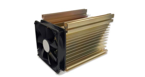
Finally, engineers often class heat sinks into “natural” convection or “forced” convection. Natural convection (Passive) heat sinks maximize surface area and conduct heat without the addition of active components. Forced Convection (Active) heat sinks are designed to utilize components such as fans and blowers to force cooler air across the fins, creating turbulence and increasing the cooling performance of the heat sink.
Heat Sink Fabrications
Stamped Board Level
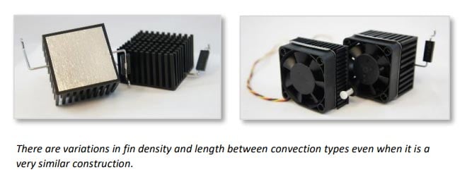
Board level heat sinks can be stamped or extruded. Stamped heat sinks are made with sheet metal that has gone through a progressive punching process where details and features are added with each stamp of metal going through the punching die.
Stamped heat sink geometries are designed for specific electronic package types to ensure optimized fit and function on a PCB. These heat sinks can be passive or active based on the addition of a fan which is typically used to increase air flow across the entire board or system.
Benefits
- Ideal for Lower Power Applications (0-5W)
- Options for Fast & Easy Assembly
- Low Cost
- Scalable High Volume
- Catalog Options for All Package Types
Trade Offs & Limitations
- Not for Applications over 5W
- Size Limitations, no larger than 50mm
- Can only be Used on One Device – not for cooling multiple heat sources
Questions to Ask Yourself
- What package or device are you cooling?
- What is the maximum ambient temperature that the device needs to operate in?
- How much power is your device dissipating?
- What is your maximum device case temperature?
- How much room do you have for your heat sink?
- What is your planned component mounting method, holes, adhesive pad, clip?
- Will there be any fans and where will they be placed?


Extruded Aluminum
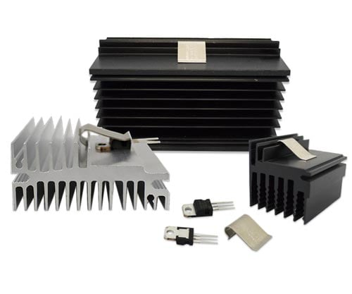
Extruded Aluminum is one of the most popular and cost-efficient fabrications. Extruded heat sinks range in size based on application, smaller for board level or larger for medium power applications. They can be designed for passive or active cooling based on fin shape and pitch. Board level extruded heat sinks are common for packages such as BGAs and FPGAs.
Choosing the right extruded heat sink is largely based on the profile needed. Extruded heats sinks are made by creating a profile die that determines fin density, pitch, and length, as well as the base height and width. Softened Aluminum is pushed through the die to create a long bar, known as a raw bar, with the same profile and size as the die. The bar is then cut into smaller, standard shaped bars/rectangles or custom lengths. These are further machined and finished to create customized heat sinks. This process is fast, cost-efficient, and scalable; which is why many consider extruded heat sinks first when searching for a solution.
Benefits
- Ideal for Low to Medium Power Applications
- Fast & Cost-Effective
- Scalable High Volume
- Simple Customizations
- One-piece construction for Limited Thermal Resistance
Trade Offs & Limitations
- Not for High Power Applications
- Size Limitations, dimensions cannot be greater than approximately 23” W, 47” L
- Finishing Limitations on larger sizes
Questions to Ask Yourself
- Are you using Natural or Forced Convection?
- Will you need machining?
- What is the maximum ambient temperature that your device will be operating in?
- How much power is your device dissipating?
- What is your maximum device case temperature?
- What is your device size and heat source footprint?
- How much room do you have for your heat sink?
Skived Fin Heat Sinks
Skiving is a fabrication constructed from a single piece of metal where layers are partially sliced from the top of the base. These layers are folded back to be perpendicular to the base and the process is repeated at regular intervals to create fins. The one-piece construction reduces thermal resistance as there is no joint or material between the fin and base. This process also enables high fin density and thin fin geometries allowing for more heat sink surface area and increased heat transfer.
Unlike extruded heat sinks, skived fin heat sinks do not rely on tooling and multiple steps; instead they utilize one cutting tool, enabling lower tooling costs, greater design flexibility, and faster prototyping.
Benefits
- Higher Efficiency Cooling & Better Performance
- Thin Fin & High Fin Density Capabilities
- Lower Tooling Cost
- Economical Copper Fabrication
Trade Offs & Limitations
- Not for High Power Applications
- Size Limitations, see dimensions
- Thin Fins can be more fragile
- Not as conducive to high volume
Questions to Ask Yourself
- Are you using Natural or Forced Convection?
- How do you plan to mount? (Push Pins most common)
- What is the maximum ambient temperature that your device will be operating in?
- How much power is your device dissipating?
- What is your maximum device case temperature?
- How much room do you have for your heat sink?
- Do you plan on scaling quickly?

Bonded Fin and Brazed Fin Heat Sinks
A bonded fin heat sink is a two-piece assembly consisting of an extruded or machined base with grooves or slots and fins that are attached with a thermally conductive bonding agent, typically epoxy or soldering. For increased structural integrity and improved thermal performance, these constructions are sometimes brazed to strengthen the thermal and mechanical bond.
Fins are typically punched from coil stock or cut from thin plate stock while bases are often extruded, die cast, or machined. Bases may also include additional thermal integrations such as embedded heat pipes or vapor chambers for higher performance. By enabling a higher number of longer fins and additional customizations, bonded heat sinks offer a higher performance with more surface area in a smaller footprint.
Benefits
- Smaller Footprint for Applications with Limited Space
- High Thermal Performance
- Good for Forced Convection, No limit on Air Flow length
- Tight Fin Pitch
- High Fin Aspect Ratio
- Easily Integrated, High Design Flexibility
- Lower Tooling Costs
Trade Offs & Limitations
- Not for Applications with High Vibration or Shock
- Cannot be used when the thermal resistance is required to be below 0.01°C/W
Questions to Ask Yourself
- How much power needs to be dissipated?
- What is the footprint and location of the heat source?
- What is the ambient temperature and max heat sink temp? (or needed thermal resistance)
- What are the geometrical or weight constraints, overall dimensions?
- Do you need a fan?
- What are your material preferences?
- What is your target cost?


Zipper Fin Heat Sinks
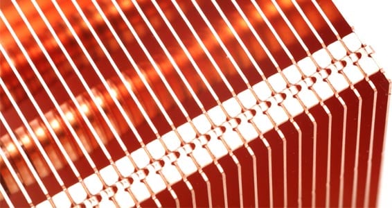
Zipper fin stacks are made from a series of individual stamped sheet metal fins that are folded and zipped together using interlocking features. Fin lengths and gaps vary based on the stamping die. Fins can be closed to create a finned duct or left open for multi-directional air flow based on application requirements. The fin stack is typically soldered, brazed, or epoxied to a heat sink base or heat pipes for a full thermal assembly. The joining of the fins at the top and bottom creates increased mechanical stability for more durable heat sinks.
Zipper fin stacks offer a high level of design flexibility that enables their use in highly integrated solutions with a range of technologies from embedded and transport heat pipes and vapor chambers to fans and larger systems.
Benefits
- High Thermal Performance
- Ideal for Forced Convection
- Easily Integrated, High Design Flexibility
- Lower Tooling Costs
- Lighter Weight
- Can be used to increase Heat Pipe Efficiency
- Increased Mechanical Integrity
Trade-Offs & Limitations
- Some limits to Low Thermal Resistance Requirements
Questions to Ask Yourself
- Are you utilizing forced convection?
- How much power needs to be dissipated?
- What is the footprint and location of the heat source? Do you have vertical space?
- What is the ambient temperature and max heat sink temp? (or needed thermal resistance)
- What are the geometrical or weight constraints, overall dimensions?
- Are you considering heat pipes?
Folded Fin
Folded fins are constructed by putting sheets of metal through a folding process to create various geometries with increased surface area. Although these fins can be used within a range of technologies including liquid cold plates; they are most often bonded or brazed to a base to create a heat sink.
Benefits
- Increased Surface Area and Fin Efficiency
- High heat Flux Density
- More Material Options
- Light Weight
Trade Offs & Limitations
- Best when air is ducted directly to heat sink
- Potential to incur higher costs

Die Cast Heat Sinks
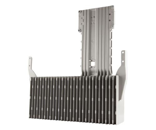
Die cast heat sinks are a single-piece construction. They are primarily manufactured in high volumes for applications that are weight sensitive, require superior cosmetic surface quality or have highly complex geometries. These solutions are made by pouring a thermally conductive alloy into a custom mold in near-net shape and are then lightly machined and finished for the final product.
Benefits
- Ideal for high volume, higher performance applications
- Suited for complex geometries
- Low to No Thermal Resistance
Trade Offs & Limitations
- High Initial One-Time Tooling Costs
Additional Components
Heat sinks can be easily integrated with other thermal technologies to greatly improve their performance. The most popular technologies utilized with heat sinks are thermal interface materials, air movers such as fans and blowers, heat pipes and vapor chambers. These various solutions can decrease thermal resistance, improve heat spreading and base cooling performance, increase fin efficiency, and ensure full optimization of your heat sink construction.
Thermal Interface Materials
Thermal interface materials (TIMs) range from gap filling pads to thermal grease and films. A thermal interface material is a conductive material applied between the heat sink and heat source to decrease thermal resistance and increase heat spreading. No matter how smooth the heat sink base is, when placed directly on the heat source there will be tiny air gaps between the device and heat sink that hinder heat transfer. These materials fill the air pockets to improve heat transfer.
Thermal Grease
- Most commonly used TIM
- Low interface resistance
- Best for flat surfaces
- Screened on by Manufacturer (like print screening)
Gap Fillers
- Elastomeric sheets, silicone or silicone free
- Varying thicknesses
- Can be used for multiple devices of varying heights on one heat sink
- Accommodates tolerance stack ups
- Can be electrically isolating
Adhesives and Epoxies
- High thermal conductivity compound that cures and hardens
- Can create a mechanical bond as well as decrease interface resistance
- Thermal tapes
- Available in rolls form or applied directly by Manufacturer
Phase Change
- Wax like material that melts at a specific temperature (typically 50-65°C)
- Extremely thin bond with extremely low interface resistance
- Cleaner than grease or epoxy
- Requires spring mounting force
Films and Pads
- Thin materials that conduct heat
- Typically flexible
- Best for electric isolation
- Graphite Exceptions: Not flexible, electrically isolating, and not reusable, but offers the best heat spreading
Hardware
- Thermally conductive ceramics, generally aluminum oxide
- Electrical isolation
Fans & Blowers
Fans are the simplest and most cost-efficient method to increase thermal performance. By adding a fan or blower you can increase air flow and cooling within the same footprint. Fans are customizable with varying speeds, voltages, and function types and are the first option to consider for most applications where a passive solution is not a key requirement. Fan trays are utilized in higher power applications for cost-efficient, high-performance cooling.
Blowers also vary in size and usage and are ideal for hot spot cooling in consumer electronics as they can be designed very thin with localized, highly directional cooling. Or blowers come in larger profiles that are designed for higher performance cooling with lower acoustics for applications like enterprise computing facilities and rack cooling.
Questions to Ask Yourself
- How much air flow is required in CFM?
- What DC voltage do you need, 5V, 12V, 24V, 48V (limited availability for AC voltage)
- What are your size constraints? (height, length, width)?
- Do you require additional wire options for controls?
- Do you have noise constraints? If so what decibel?
- Do you have any system level pressure requirements, usually measured as pressure drop?
- What environmental conditions will the fan be operating in? (ex. Outdoors, dust or rain exposure)

Heat Pipes & Vapor Chambers
Heat pipes and vapor chambers are passive two-phase cooling technologies. A heat pipe features a wick, most often sintered copper, that is added to the inside of a hollow pipe, also typically copper. A very small amount of water or fluid is placed inside the heat pipe and it is vacuum sealed.
When the heat source comes in contact with the heat pipe, the fluid evaporates and moves away from the heat source. Heat is transferred away from the heat source to a dissipation point and the liquid condenses in the heat pipe, releasing the heat. This enables much faster heat transfer and dispersal compared to solid metal.
Vapor chambers are similarly manufactured but have a planar geometry for improved heat spreading. When utilized in an integrated heat sink assembly, vapor chambers are embedded in the base to optimize heat transfer across the full heat sink footprint. Vapor chambers are ideal for varying device types and skylines.
Heat pipes can be used to improve heat sink fin efficiency by connecting the base to another point in the fin stack to better utilize the entire fin height. However, they are most often utilized within a heat sink for base heat spreading similar to vapor chambers. Heat pipes can be placed to accommodate mounting and multiple heat sources in an optimal design.
What Is Next?
Heat sinks will continue to be an integral part of thermal management systems and there are many more heat sink fabrication and design possibilities than most engineers realize. While heat sink basics are fairly standard, the number of options and customizations today go far beyond traditional heat sinks that have been used for decades. Many do not realize that by utilizing the optimal fabrication method with correct customization options, they could be saving time, money, space, and weight while vastly improving cooling and device performance.
Boyd has designed heat sinks for decades; since the first personal and enterprise electronics were introduced and well before the advent of the Internet as we know it. Heat sink technology has progressed significantly over that time with new constructions, technologies, and manufacturing capabilities. This trend will continue as thermal management needs evolve. New materials, higher performing constructions, and innovative technology integrations are entering the market as thermal solutions evolve.
Boyd’s decades of innovation expertise, experience, resources, and unique approach to integrating multiple functionalities into streamlined products will continue to keep the company on the forefront of thermal innovation and continually improved manufacturing methodologies. If you are ready to improve or retrofit your older model heat sinks or are looking to tackle new challenges for the next generation, start by contacting Boyd to learn more about heat sink constructions, customizations, and other possibilities for better optimized cooling.
Have questions? We’re ready to help!
