Home » Blog » Liquid Cooling System Pump Overview

Liquid Cooling System Pump Overview

Glowing liquid cooled futuristic hyper fast computer CPU.

Last updated Apr 16, 2024 | Published on Aug 9, 2019

Complex systems that utilize liquid flow rely on leak-free systems, dependable liquid containment, transport, and sealing solutions. These active systems utilize pumps to push liquid through hoses and tubing between components like reservoirs and tanks, heat exchangers, and liquid cold plates.

Centrifugal Pump Overview

Reliable Pumps for Liquid Cooling Systems

Centrifugal-Pump-Exploded-Diagram

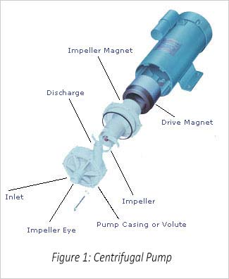
The term “centrifugal pump” encompasses a multitude of pump technologies. Centrifugal means “directed or moving away from a center or axis”, therefore a centrifugal pump uses a rotating impeller to move the fluid outward. Fluid enters the pump and is drawn into the eye, or center, of the impeller and then is forced outward through the vanes (blades) via centrifugal force generated by the rotating action of the impeller. The fluid is forced to the outside of the pump casing (or volute) and out the pump’s discharge (see figure 1). The flow of a centrifugal pump depends on the system pressure drop: the higher the pressure drop, the lower the flow.

Many of Boyd’s liquid cooling systems use seal-less, magnetically-driven centrifugal pumps, also known as mag-drives. Magnetically driven pumps use two magnets to drive the impeller. One magnet is attached to the motor shaft, generally referred to as the “drive magnet”. The other magnet is attached to the impeller (the “driven” or “impeller” magnet). The drive magnet spins causing the impeller magnet, and therefore impeller, to spin at the same rate. This pump design eliminates pump seals which often wear out from the friction caused by the rotation of the motor shaft and are a source of leakage. In our centrifugal pumps, the drive magnet is integrally molded into the impeller and thermoplastically coated to ensure zero contamination of the pump fluid. Thus, “mag-drive” ensures pump integrity and eliminates any possibility of shaft or seal leakage.

Magnetically-driven centrifugal pumps have many features that make them preferred for chiller/cooling system applications. When operated properly, they do not have any significant wear items therefore the centrifugal pump’s life will significantly exceed that of positive displacement pumps and centrifugal pumps with seals. Also, this design does not generate particles that could clog the system’s filters so the pump’s performance will not change over time. All pumps will impart some heat to the fluid but it is important to minimize heat added from the pump to ensure the recirculating chiller has tight temperature stability. Since mag-drive pumps have minimal frictional surfaces to generate heat, they transfer far less heat to the fluid than other pump styles.

Long, maintenance-free service life, combined with the other design benefits have made magnetically-driven centrifugal pumps a leading choice for Boyd’s liquid cooling systems.

Positive Displacement Pump Advantages and Operating Principles

How PDP Pumps Work and When to Use Them in Your System

Cooling-System-PDP-Pump

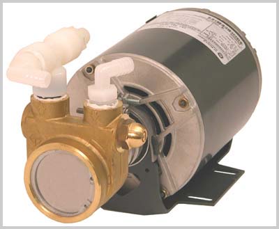
Designed to move liquid by pressurizing it, positive displacement (PD) pumps come in many configurations, such as rotary vane, gear, screw, progressive cavity, Archimedes’ screw, piston, and plunger. Historically, some of the very first pumps, invented thousands of years ago for primitive irrigation purposes, were positive displacement designs. Numerous Boyd refrigeration systems use the rotary vane positive displacement configuration. Other applications for this type of pump include post-mix beverage dispensers, espresso coffee machines, reverse osmosis water filtration systems, glycol cooling loops for beer, and welding torch coolers.

Positive-Displacement-Pump-Operation-Diagram

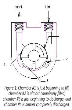
The working parts of Boyd’s positive displacement pumps are made from brass or stainless steel and carbon graphite materials, all machined to the high precision required for reliable operation. These pumps operate by filling and discharging variable volume chambers formed by graphite vanes, which slide in and out along machined radial slots in the rotor. The rotor and vane assembly fits into a graphite jacket. The rotor and jacket are offset to create an eccentric geometry that is essential to pump operation. (See Figure 1.)

When the rotor rotates (typically at 1725 revolutions per second), eccentric geometry causes the vanes to slide inward along their grooves, thereby shrinking the volume of each chamber as it moves from the inlet to the outlet. Because the fluid being pumped is not easily compressed, it is squeezed out of the chamber when it reaches the pump outlet.

Note that as the rotor turns and chamber volume changes, the vanes “float” in their slot. A combination of centrifugal force and hydraulic pressure forces the vanes outward so that they remain in contact with the housing’s inner surface and, hence, provide an effective seal. A very thin layer of fluid between the vane and jacket keeps friction to a minimum.

These positive displacement pumps are self-priming. Unlike centrifugal or turbine pumps, flow rate is steady regardless of system pressure drop. To avoid system over pressurization, the pump incorporates a relief valve set to bypass flow at 60 psi.

Positive displacement pumps are very cost-effective. For our recirculating chillers, Boyd offers these pumps with flow rates from 1.3 up to 10 gallons per minute. Smaller pumps are available with either a brass or stainless steel housing. Brass is good for most applications; stainless steel is recommended for deionized or high purity water. If you have questions about which pump will work best in your application, contact one of our applications engineers.

Learn more about Boyd’s Ambient Liquid Cooling Systems and Recirculating Chillers that leverage Positive Displacement Pumps.

Regenerative Turbine Pump Introduction

How Regenerative Turbine Pumps Work and Their Advantages

Centrifugal-Pump-Diagram

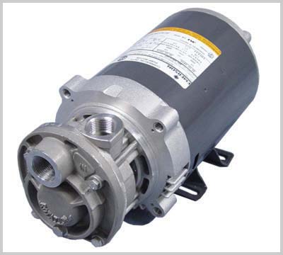
Boyd’s TB-5 turbine pump, offered with recirculating chillers, is a regenerative turbine pump.

Regenerative turbine pumps are often classified in the general category of pumps known as centrifugal. While this type of pump does borrow many of its operating principles from the “garden variety” centrifugal pump, the similarities end there because its performance characteristics are substantially different.

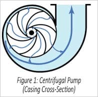
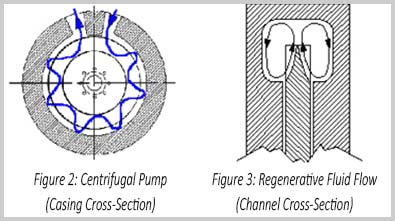
In a common centrifugal pump, fluid enters the center of the impeller (the eye) and is given a “push” by one of usually 4 to 8 rotating vanes, which impart a centrifugal force on the fluid (see Figure 1). This fluid force is collected at the periphery of the impeller, called the volute, and is redirected towards the pump discharge to provide flow and pressure. In a regenerative turbine, fluid enters the impeller much closer to its periphery where the first of a set of between 50 and 120 very small vanes gives the fluid a small push of centrifugal force in the radial direction towards the impeller periphery, much like a centrifugal pump.

Regenerative-Turbine-Pump-Casing-Channel-Cross-Section

Instead of collecting the fluid force and redirecting it immediately out the pump discharge like a centrifugal pump, the water channel, which surrounds the turbine impeller, is shaped to deflect the fluid in a circular path back towards the inside diameter of the impeller vanes (see figures 2 & 3). Here it receives a second push of centrifugal force that increases the fluid velocity which produces the potential pressure capability of the fluid. The term used to describe these multiple helical/circular round trips is called regeneration, giving this turbine pump its regenerative nature. This regeneration principle is the key to the high pressure-producing characteristic of the regenerative turbine versus the centrifugal pump. In effect, the regenerative turbine achieves similar pressure performance to a multiple stage centrifugal pump, but with only one impeller and a much simpler casing design.
Regenerative turbine pumps are preferred in applications where high pressure and compact design are desired. The typical pressure versus flow or head-capacity curve of a regenerative turbine is steep, so these pumps can easily overcome line restrictions, such as temporary blockages or the friction of long lengths of piping or tubing. Steep pressure characteristic means that large changes in pressure or restriction have relatively little effect in flow rate. Another important characteristic of the regenerative turbine is pulsation free flow.

For high-pressure applications, positive displacement pumps (PD) like piston, diaphragm, or gear pumps are also an option, however they typically suffer from two significant drawbacks. Many PD pumps have a pulsating flow output that can cause inconsistent performance in the end application, as well as, vibration, mechanical damage, and cavitation effects. Positive Displacement pumps also tend to be mechanically intensive and often have friction and wear problems that increase maintenance and repair costs. Regenerative turbines do not suffer from either of these issues.

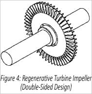
Within the realm of available regenerative turbine pumps, Boyd’s pump vendor has added several features to provide additional capability and functionality. The first is the use of a double-sided floating turbine impeller design (see Figure 4). As pressure develops equally on both sides of the impeller, a thin hydrodynamic fluid film forms between the impeller and the casing. This film helps prevent impeller wear and causes the impeller to self-adjust to its optimum axial position.

Regenerative-Turbine-Pump-Impeller

An additional benefit of the balanced floating impeller is that very little axial thrust is applied to the motor shaft, which promotes long motor bearing life. These pumps have also undergone substantial performance optimizations to provide the highest pressure capabilities, while still maintaining optimal efficiency. Another feature of these pumps is their excellent low NPSH (net positive suction head) requirements. Where applications require the units to pump fluids at temperatures very close to their boiling points or pumping low vapor pressure fluids these pumps offer a specially designed pump inlet that gently accelerates the fluid to water channel velocity, dramatically reducing cavitation effects. Even if cavitation occurs, or the fluid already contains entrained vapor, these turbines can handle over 50% vapor by volume. The pumps are also offered with a wide variety of metallurgies and elastomers in easy to repair mechanical seal or sealless configurations.

Choosing a Recirculating Chiller Pump

Choose the Correct Pump for Your Recirculating Chiller

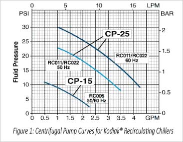
Choosing the right type of pump is critical when configuring a Kodiak a recirculating chiller to meet your requirements. Using your system’s pressure drop as the basic decision rule should help.

Ask yourself, “What is my system’s pressure drop?” Overlay your system’s pressure versus flow curve onto the chiller’s pump curve. The intersection of the two curves indicates the expected flow through your system using this pump. Once you know the expected flow you can follow the Selecting a Recirculating Chiller example to ensure the system has enough capacity to remove your heat load. You may need to check several curves to find one which provides enough flow.

If you don’t know your system’s pressure drop, a positive displacement (PD) pump is recommended. The flow rate for a PD pump is independent of the system pressure drop. For system safety, this pump has an internal bypass which is factory set at 90 PSI. Therefore, if your system pressure drop is greater than 90 PSI this pump will operate in bypass mode. You will need to reduce your system’s pressure drop by using shorter hoses with large diameters.

Cooling-System-Turbine-Pump

Centrifugal-Pump-Curves-Graph

Pump Filters

Positive Displacement pumps are sensitive to particles in the water system. If you opt for a positive displacement pump, you will want to include a water filter. We recommend that you check the water filter weekly if you include a water filter on your recirculating chiller. With a new system the filter quickly accumulates foreign matter introduced during system setup which can lead to a decrease in system performance. Inspect the filter cartridge one day after you set up a new system to ensure the filter is clean and the system runs at maximum capacity. After this initial filter inspection, check the filter weekly. We recommend you have a supply of replacement filters on hand. To further prolong the pump life we recommend you periodically inspect and clean the pump strainer. Check your manual for recommended frequency.

Water filters and deionization cartridges are not recommended with centrifugal pumps. They increase the pressure drop too much, thereby reducing the flow. If you need a water filter or a deionization cartridge, we recommend you move to a turbine pump which is less affected by pressure drop.

Pump Life

Positive Displacement Pumps have graphite fins which as mentioned above are sensitive to particulates. In addition to recommending a water filter, we suggest you swap out the pump every 8,000 – 10,000 hours of use. This will avoid damaging the unit and cost associated with excessive downtime.

Centrifugal and Turbine pumps are more tolerant of particles in the water stream and therefore have a longer lifespan than PD pumps. We recommend these pumps are replaced every 28,000 hours.

Pump Cost

Boyd’s standard chiller contains a positive displacement pump. To upgrade to a centrifugal or turbine pump, there is an additional charge, depending on the pump size.

If you need additional help selecting a pump, please contact Boyd to discuss your application with our engineering team.

Related Posts

Data Center Cooling Essentials

Data Center Cooling Essentials

Data Center Cooling: The Lifeblood of Digital Infrastructure In the dynamic realm of technology, data centers serve as...

Have questions? We’re ready to help!